|
Northern
Eclipse Help Reference |
Object Parameters |
|
Morphometric & Densitometric Parameters – Subdivided into 4 groups |
|||
|
|
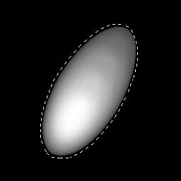
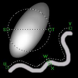
Group 1: Area & Perimeter
Primitives: 1) Area – The total number of pixels that an object occupies. This pixel count can be calibrated to real world dimensions. 2) Perimeter – The distance around the outside edge of the object. Diagonal measurements are weighted accordingly. This can also be calibrated. Derived: 1) Shape Factor – (4 * PI * Area) / (Perimeter^2). This gives an indication as to the objects shape. Circles have the greatest area to perimeter ratio and this formula will approach a value of 1 for a perfect circle. Squares are around 0.78. A thin thread-like object would have the lowest shape factor approaching 0. 2) Roundness – (Perimeter^2) / 4 * PI * Area). This gives the reciprocal value of Shape Factor for those that are used to using it. A circle will have a value slightly greater than or equal to 1. Other shapes will increase in value. 3) Equivalent Circular Diameter – 2*sqrt(Area/PI). The Diameter of the circle that would have the equivalent area as this object. 4) Equivalent Spherical Volume – (4/3)*PI*sqrt(Area/PI)^3. The Volume of the sphere that has a diameter of the Equivalent Spherical Diameter. 5) Thread Length - (Perimeter + sqrt(Perimeter^2-16*Area))/4. This gives an estimate as to the true length of a threadlike object. (Line UV). This assumes that the object to be measured is threadlike in form. Note that this is an estimate only. The estimate is fairly accurate on objects with a Shape Factor that is less than 0.25 and gets worse as the Shape Factor increases. Use this parameter when the objects are known to be threadlike and bend so that the Diameter parameter is a poor estimate of the true length. 6) Thread Width - (Perimeter - sqrt(Perimeter^2-16*Area))/4. This gives an estimate as to the true width of a threadlike object. (Line WX). This assumes that the object to be measured is threadlike in form. Note that this is an estimate only. The estimate is fairly accurate on objects with a Shape Factor that is less than 0.25 and gets worse as the Shape Factor increases. Use this parameter when the objects are known to be threadlike and bend so that the Minor Axis Diameter parameter is a poor estimate of the true width. |
||
|
|
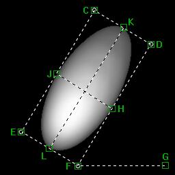
Group 2: Enclosure & Orientation
Primitives: 1) Enclosure Left – The X coordinate of point A. This is the minimum x value of all points that make up the object. 2) Enclosure Top – The Y coordinate of point A. This is the minimum y value of all points that make up the object. 3) Enclosure Right – The X coordinate of point B. This is the maximum x value of all points that make up the object. 4) Enclosure Bottom – The Y coordinate of point B. This is the maximum y value of all points that make up the object. 5) Orientation – The angle that is formed between the x-axis and the object’s major axis. (Angle DFG) 6) Diameter – The longest line through an object that is parallel to its orientation (Line KL) 7) Minor Axis Diameter – The longest line through an object that is perpendicular to its orientation. (Line HJ) 8) Diameter X1 – The x coordinate of the start of the Diameter (Point K) 9) Diameter Y1 – The y coordinate of the start of the Diameter (Point K) 10) Diameter X2 – The x coordinate of the end of the Diameter (Point L) 11) Diameter Y2 – The y coordinate of the end of the Diameter (Point L) 12) Minor Axis Diameter X1 – The x coordinate of the start of the Minor Axis Diameter (Point H) 13) Minor Axis Diameter Y1 – The y coordinate of the start of the Minor Axis Diameter (Point H) 14) Minor Axis Diameter X2 – The x coordinate of the end of the Minor Axis Diameter (Point J) 15) Minor Axis Diameter Y2 – The y coordinate of the end of the Minor Axis Diameter (Point J) Derived: 1) Elongation – Diameter / Minor Axis Diameter. This gives you a general idea of object proportions independent from perimeter or shape. |
||
|
|
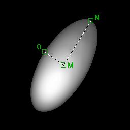
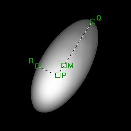
Group 3: Centroids and Radii
Primitives: 1) Centroid X – The X point in which the object is balanced in the x direction. (Point M) 2) Centroid Y – The Y point in which the object is balanced in the y direction. (Point M). Point M can be used as an unweighted Center of Gravity for the object. Contrast with Point P. 3) Maximum Radius – The longest line from the Centroid to the perimeter. 4) Minimum Radius – The shortest line from the Centroid to the perimeter. 5) Maximum Radius X – The X component of the point on the objects boundary that is furthest from its Centroid. (Point N) 6) Maximum Radius Y – The Y component of the point on the objects boundary that is furthest from its Centroid. (Point N) 7) Minimum Radius X – The X component of the point on the objects boundary that is closest to its Centroid. (Point O) 8) Minimum Radius Y – The Y component of the point on the objects boundary that is closest to its Centroid. (Point O) 9) Weighted Centroid X – The X point in which the object is balanced in the x direction using a weighting factor for each pixel corresponding to its intensity. (Point P) 10) Weighted Centroid Y – The Y point in which the object is balanced in the y direction using a weighting factor for each pixel corresponding to its intensity. (Point P) This point more accurately reflects the center of gravity of points where density is represented by intensity. 11) Weighted Maximum Radius – The longest line from the Weighted Centroid to the perimeter. 12) Weighted Minimum Radius – The shortest line from the Weighted Centroid to the perimeter. 13) Weighted Maximum Radius X – The X component of the point on the objects boundary that is furthest from its Weighted Centroid. (Point Q) 14) Weighted Maximum Radius Y – The Y component of the point on the objects boundary that is furthest from its Weighted Centroid. (Point Q) 15) Weighted Minimum Radius X – The X component of the point on the objects boundary that is closest to its Weighted Centroid. (Point R) 16) Weighted Minimum Radius Y – The Y component of the point on the objects boundary that is closest to its Weighted Centroid. (Point R) Derived: None. |
||
|
|
Group 4: Densitometric parameters Primitives: 1) Minimum Gray – The minimum gray value found within the object (not including holes) 2) Maximum Gray – The maximum gray value found within the object (not including holes) 3) Total Gray – The sum of all the individual gray values within the object (not including holes) Derived: 1) Average Gray – Total Gray / Pixel Area. The average value of all the pixels in the object. This is a mathematical average and may not necessarily correspond to any object pixel value. |
||
|
Other Parameters |
|||
|
|
1) Object # - A unique number that refers to the object. 2) Units – The units that the calibrated measurements are in. 3) Bin Classification – The name of the Bin that this object was classified as. 4) Hole Count – The number of interior holes in the object |
||

|
See Also |
|
|
References |
Table of Contents |