|
Northern
Eclipse Help Reference |
|
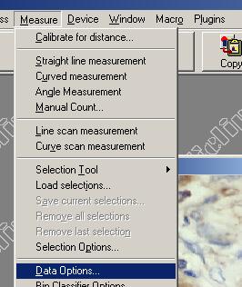
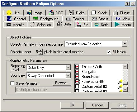
The Data options menu allows for choosing methods of object exclusion or inclusion during measuring (see measuring), morphometric data reporting choices, levels of data reporting, pixel exclusion, object perimeter mask saves, numeric data hole filling (see also Fill Holes), and morphometric boundary options.
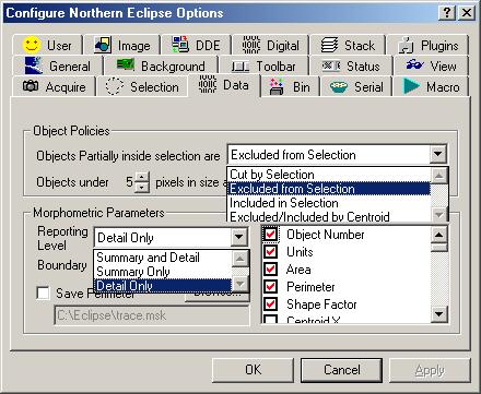
Object Policies
Cut by selection actually cuts objects under traced areas during measuring (see Trace Tool). This selection measures all objects within the traced area and cuts objects along the trace line measuring partial objects along the cut line (see Rectangle Tool). The Cut by selection option should be turned on if no thresholding (see thresholding) is done prior to measuring (see measuring). Excluded from Selection excludes all objects touching the lines of any traced areas during measuring; thus only measuring objects totally within traced areas. Included in Selection includes all objects inside a traced area. Those objects touching the traced area are not counted. Included/Excluded according to Centroid is the most statistically correct method of counting or measuring objects, because only objects with a Centroid (center of gravity point) inside the traced region is included in the count.
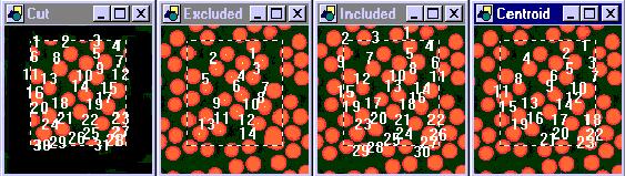
Cut Excluded Included Included/Excluded
Hint: Cut by Selection is generally not used for counting, but can be very useful for densitometry or for objects that are not easy to thresheld and therefore must be traced.
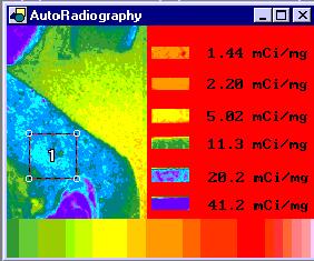
Cut by Selection (i.e. one count, and one density measurement)
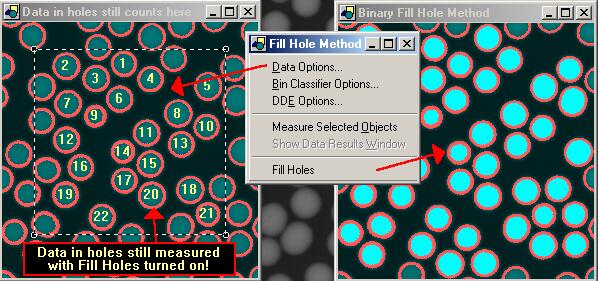
The Fill Holes check box, when checked, will take the data within an unthresheld hole (a donut) in an object as part of the area of that object from a numerically. If you would actually like to fill the hole of an object with pixel data, use Fill Holes binary method (see Fill Holes).
Morphometric Parameters
The type of data to be recorded can be selected by double clicking on or
off the red check marks beside the list of morphometric parameters. The Report level option allows for changes
in how data is reported (i.e. Summary and Detail, Summary Only or Detail Only). Summary
Only reports as implied a summary of the data only, which includes: Object
Count, Selected Area, Total Object Area, and Percent Object Area, Summary
Average Gray, Summary Total Gray, Summary Minimum Gray, Summary Maximum Gray
(and 10 Custom User Detail Equations). Detail
Only includes: Object #, Units, Area, Perimeter, Shape Factor, Centroid X,
Centroid Y, Hole Count, Diameter, Orientation, Enclosure Left, Enclosure Right,
Enclosure Top, Enclosure Bottom, Minimum Gray, Maximum Gray, Total Gray,
Average Gray, Bin Classification, Diameter X1, Diameter Y1, Diameter Y2,
Weighted Centroid X, Weighted Centroid Y, Minimum Radius, Minimum Radius X,
Minimum Radius Y, Maximum Radius, Maximum Radius Y, Maximum Radius X, Weighted
Minimum Radius, Weighted Minimum Radius Y, Weighted Minimum Radius X, Weighted
Maximum Radius, Weighted Maximum Radius Y, Weighted Maximum Radius X, Minor
Axis Diameter, Minor Axis
Diameter, Minor Axis Diameter X1, Minor Axis Diameter Y1, Minor Axis Diameter
X2, Minor Axis Diameter Y2, Equivalent Circle Diameter, Equivalent Sphere
Volume, Thread Length, Thread Width, Elongation, Roundness and 10 Custom User
Detail Equations. The Summary and Detail
option includes both Summary Only
and Detail Only (See morphometric
parameters).
The Save Perimeter check box allows perimeters (regions) to be saved as region files (file.msk). Once perimeter regions are saved, they could then be loaded later and applied to a different image (i.e. A dapi chromosome image could be thresheld and the perimeters could be saved. The saved region could then be used to measure the intensity of all the dots of a CY3 image found within the outline of the chromosomes).
Boundary This option allows the choice of an 8-way Connected or 4-way
Connected morphometric measuring algorithm to be used.
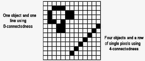
The Boundary method will be required by the user to determine when very thin ambiguous objects need to be deciphered (For further information see Computer Assisted Microscopy, by John C. Russ, 1990, pages 122 and 123).
For detail descriptions of morphometric parameters, see morphmetric definitions.
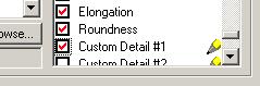
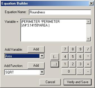
Northern Eclipse software provides users the option to create their own custom morphometric equations. It is possible to input up to 10 Detail data and 10 summery data equations. To create custom equations, click on a Custom Detail check box on the Data options tab of the Configure Eclipse Options menu.
This will bring up an Equation Builder dialog box. Known morphometric equations can be input, and once the Verify and Save button is clicked the new equation will become an option on the Data options tab with a new unique Equation Name. Equations can be input. To add an existing variable to the variable equations, click on the drop down box under Add Variable and pick a morphometric parameter. It will immediately be added to your equations. Similarly, functions can be added. The numeric keys can be used to add numbers, brackets and numeric operator values. If your equation does not verify properly you will be notified once the Verify and Save button is clicked. If it does not verify properly, check for missing or extra brackets.
|
See Also |
|
|
References |
Table of Contents |